800 Watt FD4 multi-band antenna with 1:4 super balun
Project for a multi-band antenna for the 80, 40, 20, 17, 12, 10 and 6 meter bands, including a 1:4 impedance transformer and a current balun handling 800 Watt with common mode attenuation up to 40 dB!
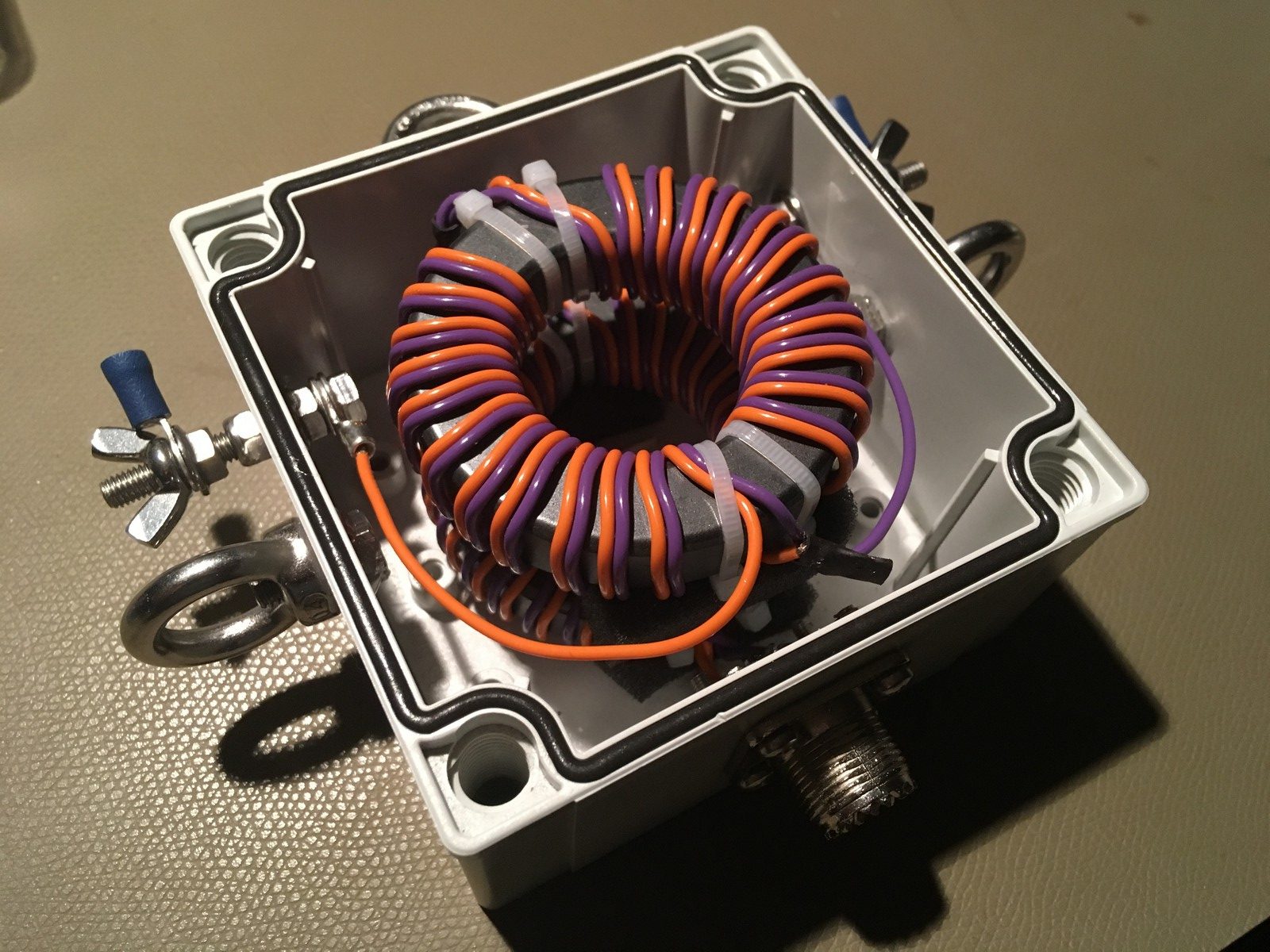
Complete balun and 1:4 impedance transformer
English: after taking a home brew end-fed antenna with me on /p trips several times, I (Thom PA9T) was looking for an antenna that gave me access to more bands. A Windom or OCF (Off Centre Fed) antenna can do that. For example, a Fritzel FD4 is an OCF antenna that has been around for a long time. Most commercial OCF designs have a 1:6 impedance transformer, without any form of balun to prevent sleeve currents. Since designing a good, high power, wide bandwidth balun is difficult and takes a lot of design iterations, I was glad that I came accros the videos of TRX Bench, and the website of Wolfgang DG0SA that inspired me to build this antenna!
Nederlands: een tijdje geleden hebben wij op de club end-fed antennes gemaakt. Deze is al enkele keren mee geweest op Scoutingkamp en vakantie, maar ik (Thom PA9T) wilde eigenlijk een betere multi-band HF-antenne. Een OCF-antenne, of Windom is een breedband antenne, met als spraakmakende voorbeeld de allombekende Fritzel FD4. Veel commercieel verkrijgbare OCF-antennes hebben echter een 1:6 impedantietransformator zonder balun. Resultaat bij de gebruik van deze antenne is dus een flinke mantelstroom. Het zelf ontwikkelen van een goede balun en goede impedantietransformator, geschikt voor veel vermogen kost veel ontwerpiteraties. Daarom was ik blij dat ik de videos van TRX Bench tegen kwam en de website van Wolfgang DG0SA.
Goals:
English: I had some specific design goals in mind for my new antenna. I wanted it to cover as many HF-bands as possible. This would imply compromises, but there are some pretty good multi-band antenna design out there. The Fritzel FD4 had my interest, because of the good performance of this antenna at our clubstation PI4UTR, and because of the article on the website of PA0FRI. Basically, I wanted the following specifications:
- As many HF-bands in one antenna, starting from the 80 meter band.
- Good common mode attenuation (>20dB)
- A perfectly flat SWR of the balun and impedance transformer
- Minimal losses in the transformers (<<1dB)
- Capable of handling contest power levels
- Large windows with an SWR lower or equal to 1:2, so an ATU can handle this.
To cover these specifications, I wanted to make a FD4 antenne, with the balun designed by TRX Bench.
Nederlands: de nieuwe antenna moest aan bepaalde eisen voldoen. Hij moest zoveel mogelijk banden afdekken. Dit betekent dat de nieuwe antenne een compromis zou worden. Er zijn echter prima multi-band ontwerpen beschikbaar. De Fritzel FD4 is een voorbeeld. Ik had interesse in deze antenne, wegens goede ervaringen op ons clubstation PI4UTR en vanwege het artikel op de website van PA0FRI. In feite wilde ik de volgende specificaties:
- Zoveel mogelijk banden in een antenne, beginnende bij de 80 meter band
- Een goede onderdrukking van mantelstromen (>20dB)
- Een vlakke SWR van de balun en impedantietransformator
- Minimale verliezen in de transformators (<<1dB)
- Geschikt voor contest vermogen
- Grote vensters met een SWR lager of gelijk aan 1:2, zodat een ATU hier mee overweg kan.
Om aan deze specificaties te voldoen, besloot ik een FD4 te maken, met de balun van TRX Bench.
1:1 current balun and 1:4 impedance transformer building instructions
English: so the FD4 antenna would be constructed using an 1:4 impedance transformer and 1:1 current balun. The design and building instructions of the balun were made by Peter of TRX Bench. With his permission, I copied his video’s how to make and measure the balun devices. Below the video’s are photo’s that show construction details of the complete balun in its housing.
Nederlands: de antenne die ik wilde maken was dus een FD4, met een 1:4 impedantietransformator en 1:1 stroombalun. Het ontwerp van de impedantietrafo en de stroombalun zijn gemaakt door Peter van TRX Bench. Met zijn toestemming heb ik onderstaande video’s ingebed in dit artikel.
Balun and impedance transformer building instructions photos
English: the videos above (special thanks to TRX Bench) show how to wind these torroids. After winding, the SWR and common mode attenuation can be measured. See the videos for instructions. My balun and impedance transformer matched the specifications in the videos. See the photos below for detailed views of the windings and measurement.
Nederlands: de videos boven (met dank aan TRX Bench) laten precies zien hoe de windingen om de torroids gewikkeld moeten worden. De balun en impedantietrafo die ik heb gemaakt, hebben precies dezelfde specificaties als in de filmpjes. Op de foto’s hieronder staan wat wikkeldetails en meetdetails.


Balun and impedance transformer measurement results and specifications
English: I have measured the SWR of the balun and the impedance transformer and the common mode attenuation of the balun. Well, in fact I have measured the return loss instead of SWR. But the SWR can be calculated from these values. See the values in the table below.
Nederlands: Ik heb de SWR van de balun en impedantietransformator gemeten, en de mantelstroomonderdrukking van de balun. Eigenlijk heb ik de return loss gemeten in plaats van SWR, maar de SWR kan worden berekend uit de return loss. Zie de waarden in de tabel hieronder.
| Frequency (MHz) | Return loss balun S11 (dB) | VSWR Balun |
| 3,5 | 44 | 1 : 1,013 |
| 7 | 39 | 1 : 1,023 |
| 14 | 32 | 1 : 1,052 |
| 28 | 28 | 1 : 1,083 |
| Frequency (MHz) | Return loss 1:4 transformer S11 (dB) | VSWR Impedance transformer |
| 3,5 | 39 | 1 : 1,023 |
| 7 | 36 | 1 : 1,023 |
| 14 | 32 | 1 : 1,052 |
| 28 | 27 | 1 : 1,094 |
| Frequency (MHz) | S21 Insertion loss balun (dB) | S21 Insertion loss balun + impedance transformer (dB)* | Loss %* |
| 3,5 | 0,05 | 0,1 | 2,329 |
| 7 | 0,07 | 0,14 | 3,276 |
| 14 | 0,08 | 0,16 | 3,753 |
| 28 | 0,16 | 0,32 | 7,647 |
*insertion loss of impedance transformer is assumed to be the same as the balun and was not actually measured
| Frequency (MHz) | S21 common mode attenuation balun (dB) |
| 3,5 | 30 |
| 7 | 32 |
| 14 | 35 |
| 28 | 39 |
Measurement details and photos
English: of course I wanted to verify the measurement results of Peter from TRX Bench. Especially because the videos do not mention anything about insertion loss. The title of the YouTube videos claim that the balun can handle 800 Watt, and Peter states that the balun can handle 1000 Watt, but that the balun will get hot. That is of course one of the reasons that PTFE insulated wiring was used. Anyway, the photos below show how to measure all the parameters in the tables above. First, I measured using a Siglent Spectrum Analyser with Tracking Generator at our clubstation PI4UTR. These results were so good, that I did not trust the measurement results. Therefore I repeated the measurement with professional equipment (Rohde and Schwarz ZNB-8 Vector Network Analyser) on my work. Both results matched Peters video’s. Hats of to TRX Bench, and to Siglent of course!
Nederlands: ik wilde de metingen van Peter van TRX Bench verifiëren. De video’s noemen geen getallen voor de verliezen. Dit wilde ik weten, omdat TRX Bench claimt 800 Watt door de balun te kunnen jagen. In de video zegt Peter bovendien dat de balun 1000 Watt aankan, maar dat hij dan wel heet wordt. Vandaar ook de PTFE isolatie om de bedrading. In de foto’s hieronder staat hoe de gegevens in de tabel hierboven verzameld zijn. In de eerste instantie heb ik gemeten met de Siglent Spectrum Analyser met Tracking Generator bij ons op de club bij clubstation PI4UTR. De resultaten waren zo goed, dat ik het niet vertrouwde, en de hele zaak nog eens heb nagemeten met professionele apparatuur op mijn werk. De resultaten kwamen overeen. Chapeau voor TRX Bench, en natuurlijk voor Siglent!

")
 Balun Siglent")
 balun Rohde Schwarz")


Balun housing construction and FD4 Antenna construction
English: I needed the balun and impedance transformer to buid an FD4 multi-band OCF antenna. See all the photos below for construction details. FD4 is of course a brand name for an Off Center Fed antenna. For a FD4, you need a good balun to prevent sleeve currents! The original FD4 has an 1:6 impedance transformer. But if you antenna is low to the ground, e.g. 10-12 meters, a 1:4 impedance transformer is also fine.
Nederlands: De balun en impedantietransformator waren nodig om een FD4 multi-band OCF antenne te maken. De foto’s hieronder laten precies zien hoe. FD4 is natuurlijk een merknaam voor een bepaalde type Off Center Fed antenne. Je hebt voor dit soort antennes een goede balun nodig om mantelstromen te voorkomen! De originele FD4 heeft een 1:6 impedantietransformator. Als je antenne laag bij de grond hangt, bijvoorbeeld 10-12 meter, is een 1:4 prima!


Homemade FD4 Antenna measurement results
English: I have measured the SWR of the antenna on several bands. Balun height was approximately 11 meters above ground, with both ends at approximately 4 meters above ground. I started with the wires on the original FD4 length, being 13,8m and 27,7m. After noticing that the resonance frequency was a bit too low on several bands, I cut it to its final length of 13,5m and 27m. Measurements done with a Maas RX-600 cross needle SWR and Power meter, connected to the antenna with 20 meters of Aircell-7. The data of the original FD4 is copied from the datasheet. A direct comparison is not possible, because I have not measured the original FD4 in my setup.
Nederlands: Ik heb de SWR van de antenne gemeten op verschillende banden. De balun hing op ongeveer 11m boven de grond, en de uiteindes van de draden op ongeveer 4m. Ik ben begonnen met de originele lengte van de FD4, 13,8m en 27,7m draad. Nadat ik merkte dat de resonantiefrequenties op veel banden te laag was, heb ik naar zijn uiteindelijke lengte van 13,5m en 27m geknipt. De metingen zijn gedaan met een Maas RX-600 kruisnaaldmeter, die met 20m Aircell-7 coax verbonden was met de antenne. De gegevens van de originele FD4 komen uit de datasheet. Een directe vergelijking gaat echter mank, want ik heb de originele FD4 niet gemeten in mijn opstelling.
| Band (m) | Frequency (MHz) | SWR FD4 version PA9T | SWR original FD4 500 Watt version |
| 80m | 3.6 | 1 : 1.6 | 1 : <5 |
| 80m | 3.8 | 1 : 1.7 | 1 : <5 |
| 40m | 7.0 | 1 : 1.5 | 1 : <2 |
| 40m | 7.1 | 1 : 1.7 | 1 : 1,39 |
| 40m | 7.2 | 1 : 2.0 | 1 : <2 |
| 20m | 14.0 | 1 : 1.7 | 1 : <2 |
| 20m | 14.1 | 1 : 1.5 | 1 : <2 |
| 20m | 14.2 | 1 : 1.35 | 1 : <2 |
| 20m | 14.3 | 1:01 | 1 : <2 |
| 17m | no data | 1 : <2 | |
| 12m | 24.89 | 1 : 1.7 | 1 : <5 |
| 12m | 24.99 | 1 : 1.5 | 1 : <5 |
| 10m | 28.0 | 1 : 1.6 | 1 : <2 |
| 10m | 28.2 | 1 : 1.25 | 1 : <2 |
| 10m | 28.7 | 1 : 1.2 | 1 : 1,71 |
| 10m | 29.6 | 1 : 1.7 | 1 : <2 |
| 6m | 50.0 | 1:01 | no data |
| 6m | 51.0 | 1 : 1.4 | no data |
| 6m | 52.0 | 1 : 1.7 | no data |
English: conclusion: the FD4 is a design with a very big window with relatively low SWR. Many band portions can be used without an antenna tuner. Overall, I was satisfied with the specifications of my antenna!
Nederlands: conclusie: de FD4 is een ontwerp met een heel groot venster met relatief lage SWR. Veel banden of delen daarvan kunnen worden gebruikt zonder antennetuner. Over het algemeen was ik tevreden met de prestaties van mijn antenne!


Bill Of Material
English: feel free to copy my antenna design. There is a list of the used materials below.
- 2x Amidon FT240-43 torroid cores
- 4x 80 cm Habia Cable E1819 NPC (Nickel Plated Copper) Orange. Buerklin part number 412331819
- 4x 80 cm Habia Cable E1819 NPC (Nickel Plated Copper) Violett. Buerklin part number 412771819
- or, as a Silver Plated alternative (better) try this for example
- 45 meter isolated, stranded copper wire 2.5 mm²
- 2x isolators, for example this one
- 1x housing Fibox PC 95/60 HG polycarbonate, 100 x 100 x 60 IP67
- 3x eye nut M6, for example this one
- 3x bolt M6 x 15 mm
- 4x wire clips for wires to 3mm, for example this one
- 1x PL-259 chassis mount (or N-type if you prefer)
-
2x bolts M5 x 40mm
-
2x wing nut M5
-
4x nut M5
- 2x lock nut M5
-
8x ring M5
-
6x cable shoe, for 2.5 mm² wire
-
4x bolts, rings and nuts for mounting the PL259 chassis part.
Nederlands: voel je vrij om mijn antenne ontwerp na te maken. Hieronder staat de materiaallijst voor de antenne.
- x Amidon FT240-43 torroid cores
- 4x 80 cm Habia Cable E1819 NPC Orange. Buerklin part number 412331819
- 4x 80 cm Habia Cable E1819 NPC Violett. Buerklin part number 412771819
- of, voor een Silver Plated alternatief (beter dan nikkel) probeer dit eens als voorbeeld
- 45 meter geïsoleerd, soepel koperdraad 2.5 mm², bijvoorbeeld deze.
- 2x isolators, bijvoorbeeld deze
- 1x behuizing Fibox PC 95/60 HG polycarbonate, 100 x 100 x 60 IP67
- 3x oogmoer M6 RVS A2 DIN 582
- 3x bout M6 x 15 mm
- 4x wire clips voor draden tot 3mm, bijvoorbeeld deze
- 1x PL-259 chassisdeel
-
2x bouten M5 x 40mm
-
2x vleugelmoer M5
-
4x moer M5
- 2x borgmoer M5
-
8x ring M5
- 6x kabelschoen voor 2.5 mm² draad
-
4x boutjes, moeren en ringen om het PL259 chassisdeel vast te maken